There are alternative methodologies for modeling and designing systems. Structured methodologies and object-oriented development are the most prominent.
1. Structured Methodologies
Structured methodologies have been used to document, analyze, and design information systems since the 1970 s. Structured refers to the fact that the techniques are step by step, with each step building on the previous one. Structured methodologies are top-down, progressing from the highest, most abstract level to the lowest level of detail—from the general to the specific.
Structured development methods are process-oriented, focusing primarily on modeling the processes, or actions that capture, store, manipulate, and distribute data as the data flow through a system. These methods separate data from processes. A separate programming procedure must be written every time someone wants to take an action on a particular piece of data. The procedures act on data that the program passes to them.
The primary tool for representing a system’s component processes and the flow of data between them is the data flow diagram (DFD). The data flow diagram offers a logical graphic model of information flow, partitioning a system into modules that show manageable levels of detail. It rigorously specifies the processes or transformations that occur within each module and the interfaces that exist between them.
Figure 13.6 shows a simple data flow diagram for a mail-in university course registration system. The rounded boxes represent processes, which portray the transformation of data. The square box represents an external entity, which is an originator or receiver of information located outside the boundaries of the system being modeled. The open rectangles represent data stores, which are either manual or automated inventories of data. The arrows represent data flows, which show the movement between processes, external entities, and data stores. They contain packets of data with the name or content of each data flow listed beside the arrow.
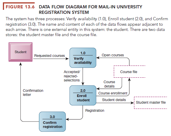
This data flow diagram shows that students submit registration forms with their name, their identification number, and the numbers of the courses they wish to take. In process 1.0, the system verifies that each course selected is still open by referencing the university’s course file. The file distinguishes courses that are open from those that have been canceled or filled. Process 1.0 then determines which of the student’s selections can be accepted or rejected. Process 2.0 enrolls the student in the courses for which he or she has been accepted. It updates the university’s course file with the student’s name and identification number and recalculates the class size. If maximum enrollment has been reached, the course number is flagged as closed. Process 2.0 also updates the university’s student master file with information about new students or changes in address. Process 3.0 then sends each student applicant a confirmation of registration letter listing the courses for which he or she is registered and noting the course selections that could not be fulfilled.
The diagrams can be used to depict higher-level processes as well as lower- level details. Through leveled data flow diagrams, a complex process can be broken down into successive levels of detail. An entire system can be divided into subsystems with a high-level data flow diagram. Each subsystem, in turn, can be divided into additional subsystems with second-level data flow diagrams, and the lower-level subsystems can be broken down again until the lowest level of detail has been reached.
Another tool for structured analysis is a data dictionary, which contains information about individual pieces of data and data groupings within a system (see Chapter 6). The data dictionary defines the contents of data flows and data stores so that systems builders understand exactly what pieces of data they contain. Process specifications describe the transformation occurring within the lowest level of the data flow diagrams. They express the logic for each process.
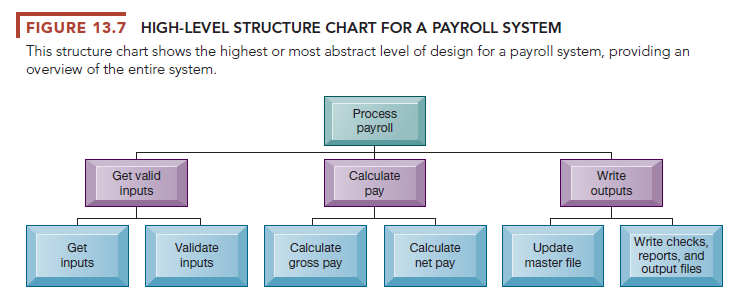
In structured methodology, software design is modeled using hierarchical structure charts. The structure chart is a top-down chart, showing each level of design, its relationship to other levels, and its place in the overall design structure. The design first considers the main function of a program or system, then breaks this function into subfunctions, and decomposes each subfunction until the lowest level of detail has been reached. Figure 13.7 shows a high-level structure chart for a payroll system. If a design has too many levels to fit onto one structure chart, it can be broken down further on more detailed structure charts. A structure chart may document one program, one system (a set of programs), or part of one program.
2. Object-Oriented Development
Structured methods are useful for modeling processes but do not handle the modeling of data well. They also treat data and processes as logically separate entities, whereas in the real world such separation seems unnatural. Different modeling conventions are used for analysis (the data flow diagram) and for design (the structure chart).
Object-oriented development addresses these issues. Object-oriented development uses the object as the basic unit of systems analysis and design. An object combines data and the specific processes that operate on those data. Data encapsulated in an object can be accessed and modified only by the operations, or methods, associated with that object. Instead of passing data to procedures, programs send a message for an object to perform an operation that is already embedded in it. The system is modeled as a collection of objects and the relationships among them. Because processing logic resides within objects rather than in separate software programs, objects must collaborate with each other to make the system work.
Object-oriented modeling is based on the concepts of class and inheritance. Objects belonging to a certain class, or general category of similar objects, have the features of that class. Classes of objects in turn can inherit all the structure and behaviors of a more general class and then add variables and behaviors unique to each object. New classes of objects are created by choosing an existing class and specifying how the new class differs from the existing class instead of starting from scratch each time.
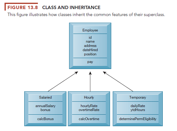
We can see how class and inheritance work in Figure 13.8, which illustrates the relationships among classes concerning employees and how they are paid. Employee is the common ancestor, or superclass, for the other three classes. Salaried, Hourly, and Temporary are subclasses of Employee. The class name is in the top compartment, the attributes for each class are in the middle portion of each box, and the list of operations is in the bottom portion of each box. The features that are shared by all employees (ID, name, address, date hired, position, and pay) are stored in the Employee superclass, whereas each subclass stores features that are specific to that particular type of employee. Specific to hourly employees, for example, are their hourly rates and overtime rates. A solid line from the subclass to the superclass is a generalization path showing that the subclasses Salaried, Hourly, and Temporary have common features that can be generalized into the superclass Employee.
Object-oriented development is more iterative and incremental than traditional structured development. During analysis, systems builders document the functional requirements of the system, specifying its most important properties and what the proposed system must do. Interactions between the system and its users are analyzed to identify objects, which include both data and processes. The object-oriented design phase describes how the objects will behave and how they will interact with one another. Similar objects are grouped together to form a class, and classes are grouped into hierarchies in which a subclass inherits the attributes and methods from its superclass.
The information system is implemented by translating the design into program code, reusing classes that are already available in a library of reusable software objects, and adding new ones created during the object-oriented design phase. Implementation may also involve the creation of an object-oriented database. The resulting system must be thoroughly tested and evaluated.
Because objects are reusable, object-oriented development could potentially reduce the time and cost of writing software because organizations can reuse software objects that have already been created as building blocks for other applications. New systems can be created by using some existing objects, changing others, and adding a few new objects. Object-oriented frameworks have been developed to provide reusable, semicomplete applications that the organization can further customize into finished applications.
3. Computer-Aided Software Engineering
Computer-aided software engineering (CASE)—sometimes called computer- aided systems engineering— provides software tools to automate the methodologies we have just described to reduce the amount of repetitive work in systems development. CASE tools provide automated graphics facilities for producing charts and diagrams, screen and report generators, data dictionaries, extensive reporting facilities, analysis and checking tools, code generators, and documentation generators. CASE tools also have capabilities for validating design diagrams and specifications. Team members can share their work easily by accessing each other’s files to review or modify what has been done. Modest productivity benefits can also be achieved if the tools are used properly, which requires organizational discipline.
Source: Laudon Kenneth C., Laudon Jane Price (2020), Management Information Systems: Managing the Digital Firm, Pearson; 16th edition.
you are in point of fact a just right webmaster. The site loading speed is amazing. It seems that you’re doing any unique trick. Also, The contents are masterpiece. you have done a wonderful process on this topic!
I really like your writing style, good information, thanks for putting up : D.