To create a database, you must understand the relationships among the data, the type of data that will be maintained in the database, how the data will be used, and how the organization will need to change to manage data from a companywide perspective. The database requires both a conceptual design and a physical design. The conceptual, or logical, design of a database is an abstract model of the database from a business perspective, whereas the physical design shows how the database is actually arranged on direct-access storage devices.
1. Normalization and Entity-Relationship Diagrams
The conceptual database design describes how the data elements in the database are to be grouped. The design process identifies relationships among data elements and the most efficient way of grouping data elements together to meet business information requirements. The process also identifies redundant data elements and the groupings of data elements required for specific application programs. Groups of data are organized, refined, and streamlined until an overall logical view of the relationships among all the data in the database emerges.
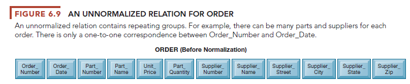
To use a relational database model effectively, complex groupings of data must be streamlined to minimize redundant data elements and awkward many- to-many relationships. The process of creating small, stable, yet flexible and adaptive data structures from complex groups of data is called normalization. Figures 6.9 and 6.10 illustrate this process.
In the particular business modeled here, an order can have more than one part, but each part is provided by only one supplier. If we build a relation called ORDER with all the fields included here, we would have to repeat the name and address of the supplier for every part on the order, even though the order is for parts from a single supplier. This relationship contains what are called repeating data groups because there can be many parts on a single order to a given supplier. A more efficient way to arrange the data is to break down ORDER into smaller relations, each of which describes a single entity. If we go step by step and normalize the relation ORDER, we emerge with the relations illustrated in Figure 6.10. You can find out more about normalization, entity-relationship diagramming, and database design in the Learning Tracks for this chapter.
Relational database systems try to enforce referential integrity rules to ensure that relationships between coupled tables remain consistent. When one table has a foreign key that points to another table, you may not add a record to the table with the foreign key unless there is a corresponding record in the linked table. In the database we examined earlier in this chapter, the foreign key Supplier_Number links the PART table to the SUPPLIER table. We may not add a new record to the PART table for a part with Supplier_Number 8266 unless there is a corresponding record in the SUPPLIER table for Supplier_Number 8266. We must also delete the corresponding record in the PART table if we delete the record in the SUPPLIER table for Supplier_Number 8266. In other words, we shouldn’t have parts from nonexistent suppliers!
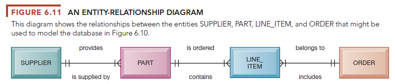
Database designers document their data model with an entity-relationship diagram, illustrated in Figure 6.11. This diagram illustrates the relationship between the entities SUPPLIER, PART, LINE_ITEM, and ORDER. The boxes represent entities. The lines connecting the boxes represent relationships. A line connecting two entities that ends in two short marks designates a one-to-one relationship. A line connecting two entities that ends with a crow’s foot topped by a short mark indicates a one-to-many relationship. Figure 6.11 shows that one ORDER can contain many LINE_ITEMs. (A PART can be ordered many times and appear many times as a line item in a single order.) Each PART can have only one SUPPLIER, but many PART can be provided by the same SUPPLIER.
It can’t be emphasized enough: If the business doesn’t get its data model right, the system won’t be able to serve the business well. The company’s systems will not be as effective as they could be because they’ll have to work with data that may be inaccurate, incomplete, or difficult to retrieve. Understanding the organization’s data and how they should be represented in a database is perhaps the most important lesson you can learn from this course.
For example, Famous Footwear, a shoe store chain with more than 800 locations in 49 states, could not achieve its goal of having “the right style of shoe in the right store for sale at the right price” because its database was not properly designed for rapidly adjusting store inventory. The company had an Oracle relational database running on a midrange computer, but the database was designed primarily for producing standard reports for management rather than for reacting to marketplace changes. Management could not obtain precise data on specific items in inventory in each of its stores. The company had to work around this problem by building a new database where the sales and inventory data could be better organized for analysis and inventory management.
Source: Laudon Kenneth C., Laudon Jane Price (2020), Management Information Systems: Managing the Digital Firm, Pearson; 16th edition.
Appreciate it for this tremendous post, I am glad I found this website on yahoo.